Arduino and pyfirmata section
Current Availability of Input and Output for FEAGI
At present, FEAGI has the capability to read both input and output. To control the output, it relies on the cortical area's ID called "o_gpio." When you activate a specific voxel within this area, it will correspond to the pin number.
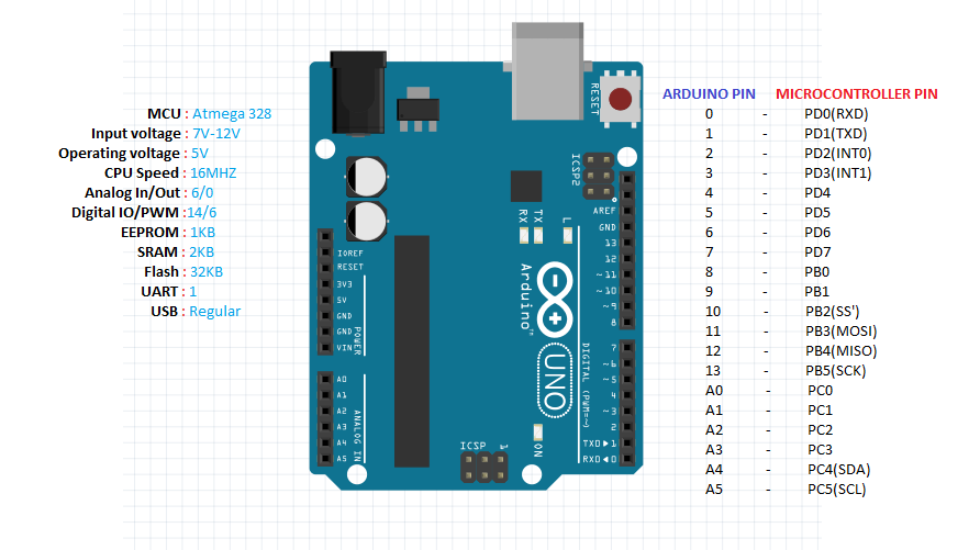

The cortical area responsible for GPIO output is named "GPIO_out." If you select, for example, 2 from the picture above, it will activate GPIO 2 as an output. There is also a cortical area's ID called "idgpio," which displays red voxels based on the data it reads.
Mapping in Arduino Pins
All pins are set to servo mode. FEAGI is extremely flexible in how you set it up.
So, when you connect a LED to digital 12 and use the cortical area called GPIO_out,
it will translate as an output until you activate 12 in the input or servo,
at which point it will change the mode. It's designed to be super flexible for users and microcontrollers.
Example with the LED (OUTPUT tutorial)
Using the image from here:
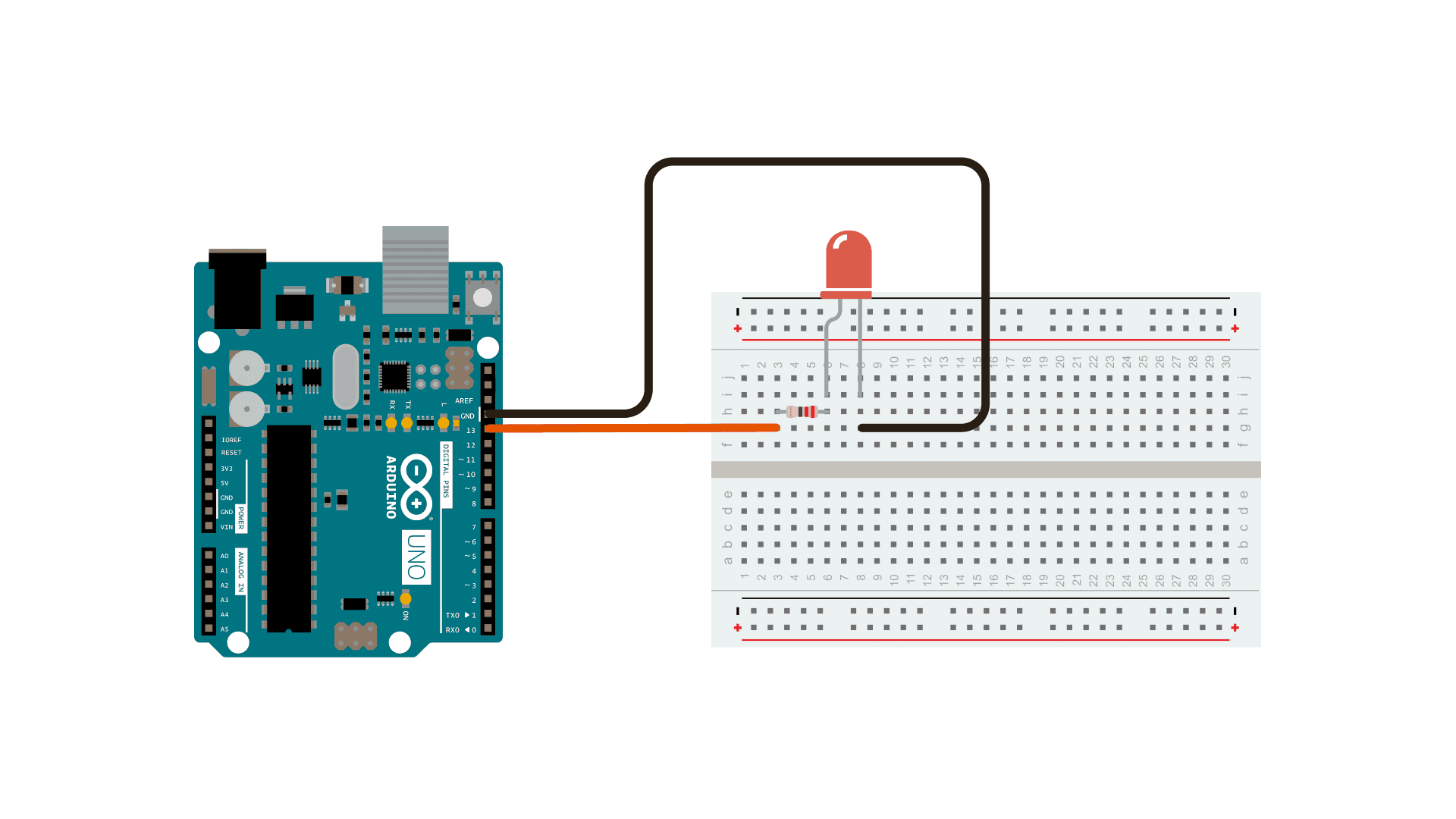
Connect the positive to digital pin 13 and also connect the ground to the negative.
Once you activate pin 13 in the GPIO_out, the LED should light up.
You can adjust how long the LED stays on by changing the refresh rate in hertz (Hz).
Example with the Switch Button (INPUT Tutorial)
Using the image from here:
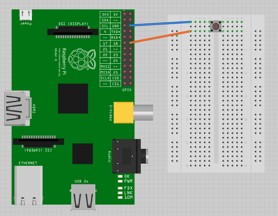
FEAGI is extremely flexible with input and output. It will automatically switch to input mode when you activate the pin in the oigpio,
indicating that the pin is now in input mode. Once activated, it will read input in real-time.
When you press the button on the switch, you should see the respective pin in GPIO_in light up.
In the diagram, the switch is waiting for voltage to reach digital pin 13.
When the voltage reaches pin 13, the corresponding pin in GPIO_in will light up.
This is an example of digital input.